
Application sector
Energy Storage
Step-up and LV distribution equipment for containerised storage sites, sized for round-trip efficiency and fast installation.
How a storage plant is connected
A storage plant connects to the grid through its PCS and a step-up transformer, cycling daily between charging, discharging and standby with power flowing in both directions. Unlike a conventional load, the transformer remains energised during standby, so its no-load loss is charged directly to auxiliary consumption and affects round-trip efficiency and project returns.
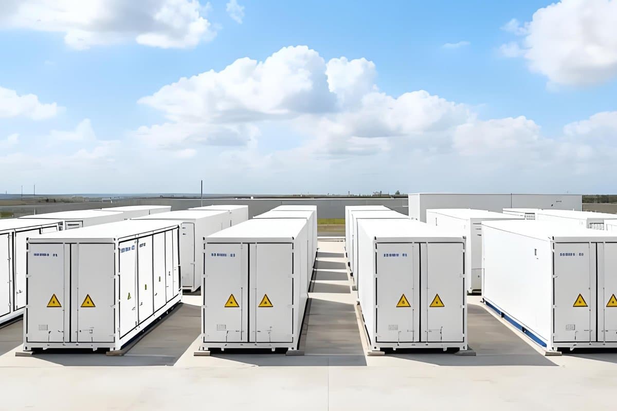
Electrochemical storage is usually built from prefabricated enclosures or containers, with battery units, PCS and step-up equipment lined up along the site — compact, and installed on a tight schedule. The equipment has to run outdoors through temperature swings, humidity and dust while keeping site wiring and later maintenance to a minimum.
What storage sites have to cope with
Equipment choices are driven by round-trip efficiency and by the pace of construction: every kilowatt-hour of auxiliary consumption dilutes the return, and every day of site work delays grid connection.
- Bidirectional operation with long standby periods, so no-load loss is charged to auxiliary consumption
- Harmonic content on the PCS side, which the vector group and winding arrangement have to keep away from the grid
- Compact container layouts that limit the footprint and transport dimensions of the step-up equipment
- Outdoor humidity, dust and temperature swings, calling for sealed construction and a high degree of protection
- Largely unattended sites, which require long maintenance-free intervals
In short, a storage site needs primary equipment that is frugal in standby, simple to wire and unlikely to be opened again once it is running.
Coreda's approach for storage sites
For PCS step-up units and the LV circuits inside the enclosures we build around fully sealed amorphous-alloy transformers, with compact substations and withdrawable LV cubicles to cut installation and maintenance work.
Recommended configuration:
- SBH15-M sealed amorphous-alloy transformer: fully oil-filled sealed design, no-load loss 70% below the group I values of GB/T 6451 and load loss 15% below the standard values, built to JB/T 10318—2002.
- ZGS11 compact pad-mounted substation (American style): fully sealed tank and fully insulated design, small and compact, suitable for both ring-main and terminal supply, with good short-circuit withstand.
- GCS withdrawable LV switchgear: rated up to 4000 A, with busbar, functional-unit and cable compartments separated from one another, covering incoming, feeder and reactive-power compensation duties.
- Dyn11 vector group: reduces the effect of harmonics on the grid and improves power quality at the connection point.
Equipment is delivered in groups that follow the container rows: one step-up circuit and one LV feeder per PCS, with the substation lifted into place so that only MV cable and communication connections remain on site.
Recommended products
Product configurations for this sector
SBH15-M
Rated capacity:
30–2500 kVA
Voltage class:
10 kV / 0.4 kV
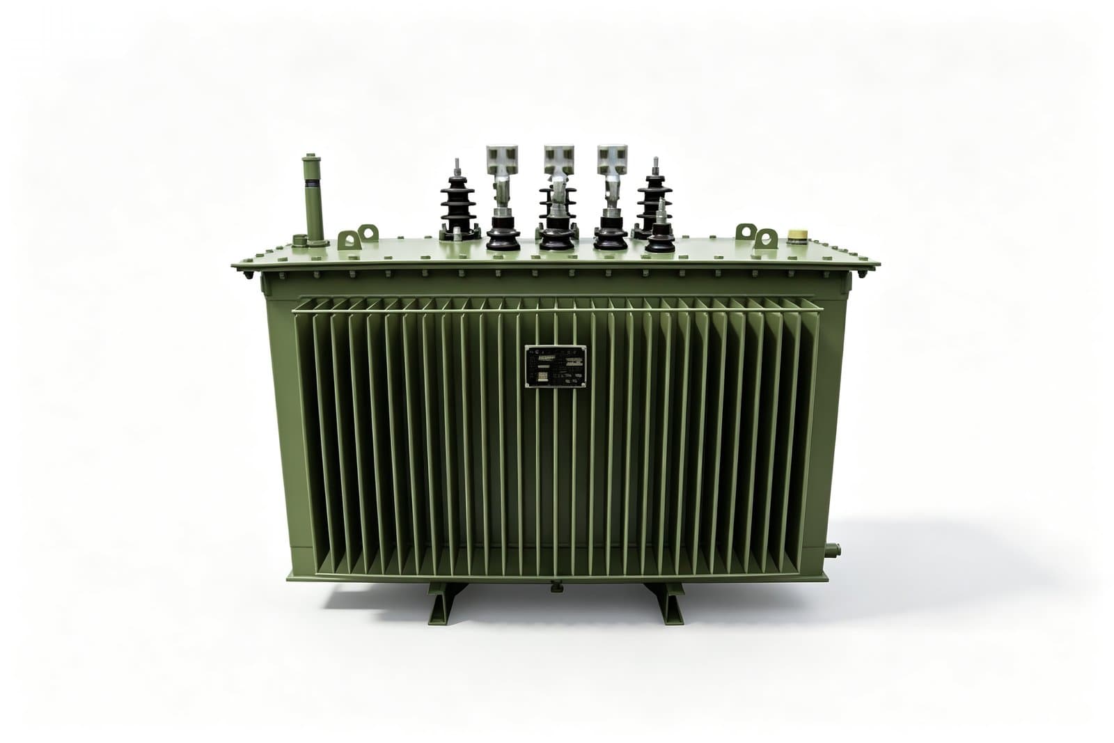
SBH15-M Sealed Amorphous-Alloy Power Transformer
Fully oil-filled sealed amorphous-alloy power transformer: no-load loss 70% below the GB/T 6451 group I values and load loss 15% below standard.
ZGS11
Rated capacity:
100–1600 kVA
HV rating:
6–11 kV (6 / 6.3 / 6.6 / 10 / 10.5 / 11 kV)
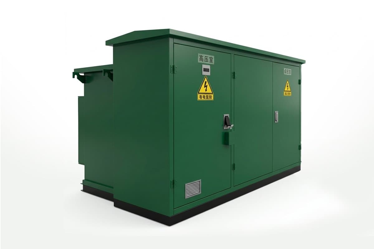
ZGS11 Combined Transformer Series (American-Style Pad-Mounted Substation)
ZGS11 combined transformers (American-style pad-mounted), 100–1600 kVA, fully sealed tank and fully insulated design, for ring-main or radial supply.
GCS
Rated voltage:
AC 380 V / 660 V, 50/60 Hz
Rated current:
≤ 4000 A
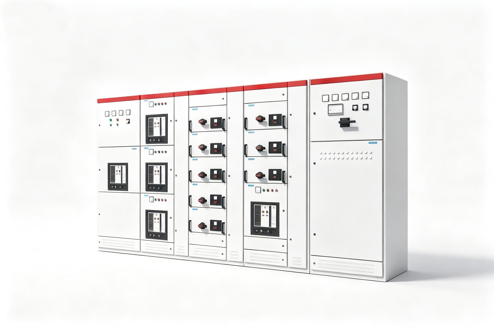
GCS AC Low-Voltage Withdrawable Switchgear
Withdrawable LV switchgear assembly for 50/60 Hz, 380/660 V networks up to 4000 A, used for incoming and feeder circuits and centralised motor control.
More sectors
Explore other application sectors
Solar PV
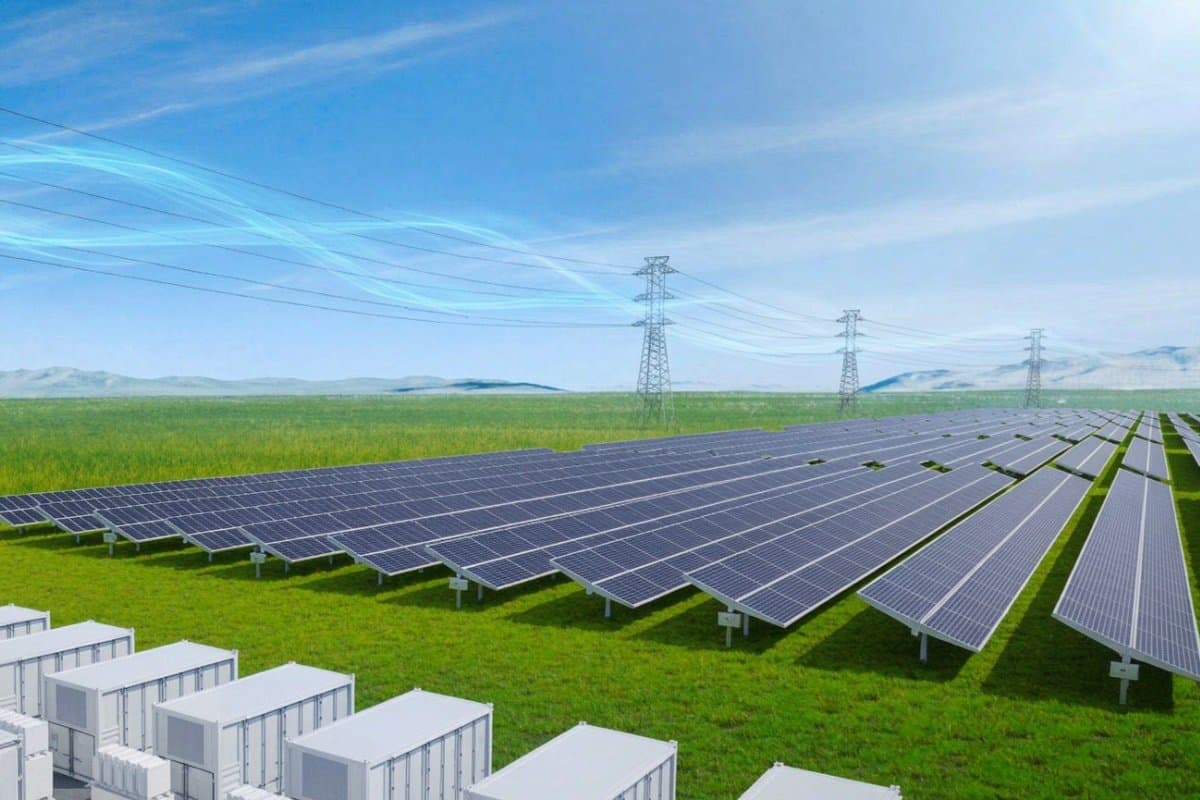
A PV plant's output follows the sun — zero at night, while the step-up transformer stays energised — so no-load loss takes a visible share of site losses. Coreda offers step-up configurations for both ground-mounted and distributed projects, combining amorphous-alloy transformers with prefabricated substations to cut site losses and the footprint of the connection point.
Typical uses
- Step-up units for ground-mounted arrays
- Rooftop and industrial-park connection points
- Step-up stage of combined PV and storage sites
Typical equipment
- Box-type substations
- Compact pad-mounted substations
- Amorphous-alloy oil-immersed transformers
- Distributed connection
Wind Power
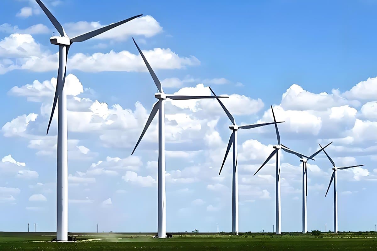
Wind turbines stay connected to the grid through low-wind and standstill periods, leaving the step-up transformer at no load or light load for long stretches, and the equipment is spread across an unattended site. Coreda delivers the step-up unit as a complete box-type substation, with amorphous-alloy or low-loss silicon-steel transformers inside to limit site losses and inspection work.
Typical uses
- Step-up units at the base of the turbine tower
- Collection circuits and site collection points
- Outdoor positions on coastal, mountain and desert sites
Typical equipment
- Box-type substations
- Amorphous-alloy oil-immersed transformers
- 35 kV collection
- Salt-fog and dust protection
Solutions and quotations
Tell us what your project needs
Send the capacity, voltage class and installation conditions, and we will come back with a selection proposal, technical data and a quotation.
- Amorphous alloy transformers
- Custom configuration
- Type-test reports
- After-sales support